Electric Current and its Circuits
4.1 Introduction
Electricity
is important in our daily life. Our household contains television, fan,
AC, tubelights etc. These all appliances need electricity to work.
4.2
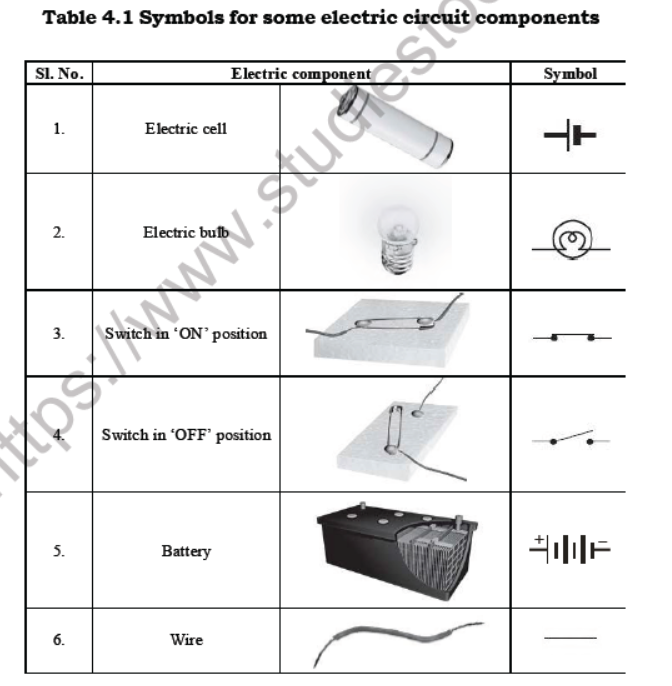
Symbols of Electric Components Some common electric components can be
represented by symbols. In Table 4.1 some electric components and their
symbols are shown. An electric cell has a positive terminal and a
negative terminal. In the symbol of the electric cell, the longer line
represents the positive terminal and the thicker, shorter line
represents the negative terminal.
For a switch the
‘ON’ position and the ‘OFF’ position are represented by the symbols as
shown. The wires used to connect the various components in a circuit are
represented by lines.
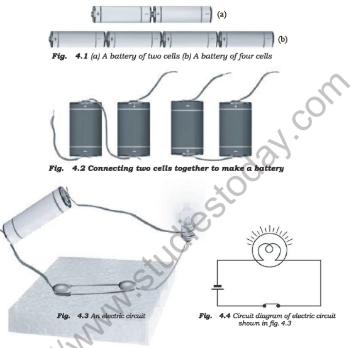
Notice
that the positive terminal of one cell is connected to the negative
terminal of the next cell. Such a combination of two or more cells is
called a battery.
In
the bulb there is a thin wire, called the filament which glows when an
electric current passes through it. When the bulb gets fused, its
filament is broken.
4.3 Electrical circuit :
Electrical circuit is an electrical network which provides an
electrical path for the flow electrical current and electrical charge.
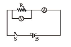
An electrical circuit generally consists of various electrical components and electrical load.
In the above figure, various electrical components have been shown.
(i) Battery/Cell (B) : A cell or battery acts as the source of charge/current in an electrical circuit.
(ii) Electrical switch (S) : An electrical switch is a device which is used to either make or break the path for the flow of current.
(iii) Electrical load (RL) :
The external element or object across which all the electrical
measurements or calculation are made. This is the chief element which is
used for the conversion of the electrical energy into the required form
of energy for use. Example : bulb, heater, etc.
(iv) Voltmeter (V) :
This is an electrical instrument that is used to measure the potential
difference between the two points in an electrical circuit. It is to be
noted that voltmenter is always connected in parallel to the two points,
across which the potential difference is to be calculated.
(v) Ammeter (A) :
This is an electrical instrument that is used to measure the electrical
current flowing through a load or electrical path. An ammeter is always
connected in series with the
electrical path through the electrical current is to be measured.
Note :–
(i)
In a battery, the positive terminal is considered to be the starting
point of charge/current while negative terminal as the ending point.
(ii) Outside the battery current flows from positive to negative terminal whereas the direction is reversed inside the battery.
(iii) The switch may be in ‘ON’ or ‘OFF’ state depending on whether it is closed or open.
(iv)
Whether the current/charge will flow through the electrical load or
not, is decided by the topology of the elecrical circuit and position of
electrical switch.
4.4 (i) Electric Charge :
Electric charge can be defined as the physical factor that arives due
to deficiency or excess of electrons in a substance. This factor is
responsible for the electrical effects.
(ii) Electric Current : The electric current is defined as rate of flow of charge. Mathematically, Electric current,
I = Charge (Q) / Time (t)
Electric current is scalar quantity. Its unit is Ampere (A).
4.5 Electrical Potential Difference :
The electrical potential difference between two points is the
compelling force which causes the electrical charges and hence the
electric current to flow through
an electrical path.
Theoretically, it is defined as the amount of work done in moving a unit
positive charge between two points without imparting any kinetic energy
in it.
i.e., VA VB WAB
/q ; where, VA – VB = Potential difference between two points A and B q
= unit positive charge, WAB = Amount of work done in moving the charge
between the point A
and B.
S.I. unit of electrical potential difference in volt (V).
Electrical potential :
The electric potential at a point is defined as the amount of work done
in bringing a unit positive charge from infinity to the point of
consideration. S.I. unit of electric potential is same as that of
potential difference i.e., Volt (V).
Note :
(i)
Electrical potential difference is a practical term whereas the
electric potential is a referential term in which one of the pont is
considered to be as infinity.
(ii) Electric
current and positive charges flows from the high potential to low
potential in an electrical circuit, outside the battery.
(iii)
Electrons (negative charge) flows from low potential to high potential.
Therefore, the direction of flow of current is taken to be opposite to
the direction of flow of electrons.
4.6 Ohm’ Law :
Ohm’s
law states that at constant physical condition (i.e., at constant
temperature), the electrical current flowing through a conductor is
directly proportional to the electrical potential difference between the
two ends of the conductor.
i.e., I ∝ (VA - VB)(where VA - VB = V)
or I ∝ V
or , I = V/R
Where R is the constant of proportionality called electrical resistance of the conductor.
Electrical Resistance : Electrical resistance is the material property which obstructs the flow of current/charge through the material.
(i) It depends on the nature of the material
(ii) It also depends on the temperature.
The SI unit of resistance is Ohm. Symbol of Ohm in Ω.
Note:- Ohm’s
law is defined at constnat temperature because resistance of a mateiral
changes with the change in temperature and hence affects the flow of
current though the conductor.
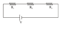
4.7 Combination of Resistances
We
can combine resistances in two ways. The first combination is called
series combination and second combination is called parallel
combination.
Series Combination
4.8 Heating effect of current
The
wire gets hot when an electric current passes through it. This is
called heating effect of the electric current. You might have seen an
electric room heater or an electric heater used for cooking. All these
contain a coil of wire. This coil of wire is called an element.
Wires
made from some special materials melt quickly and break when large
electric currents are passed through them. These wires are used for
making electric fuses. In all building fuses are inserted in all
electrical circuits. There is a maximum limit on the current which can
safely flow through a circuit. If by accident the current exceeds this
safe limit, the wires may become overheated and may cause fire. If a
proper fuse is there in the circuit, it will blow off and break the
circuit. A fuse is thus a safety device which prevents damages to
electrical circuits and possible fires.

4.9 Magnetic effect of electric current
Take
the cardboard tray from inside a discarded matchbox. Wrap an electric
wire a few times around the cardboard tray. Place a small compass needle
inside it. Now connect the free ends of this wire to an electric cell
through a switch.